Nulla facilisi. In vel mauris risus.
Praesent non velit ut libero condimentum pulvinar sed vitae tellus.
Vestibulum id tristique elit. Suspendisse posuere rutrum sodales. Nam id elit ac sem iaculis lacinia posuere vitae metus.
In our new series, Stories from Tech Support, we interviewed members of our Technical Support and Field Engineering Teams to learn about the challenges they encounter in the field and how they helped customers overcome their challenges. This series was created to share their experiences and to help others overcome similar problems.
Our first story comes from Christian, a Technical Support Engineer here at Moxa. In the story, he tells us about how he worked with a distributor to help them trouble-shoot and resolve issues that one of their customers were having.
The Client
The end customer is a factory in Western Europe that was under-going an expansion of their plant, adding in new equipment and in effect, extending their current network. The client built a separate network for the new part of the factory segment and wanted to connect it as a sub-network to the main network, this way the new part of the plant could be accessed from the control room.
The Problem
Christian received a time-sensitive request from the distributor and customer when they were having troubles communicating with the end device from the control room. Although the expansion was not yet complete, it would be soon and the network needed to be tested and ready so the machines could be connected.

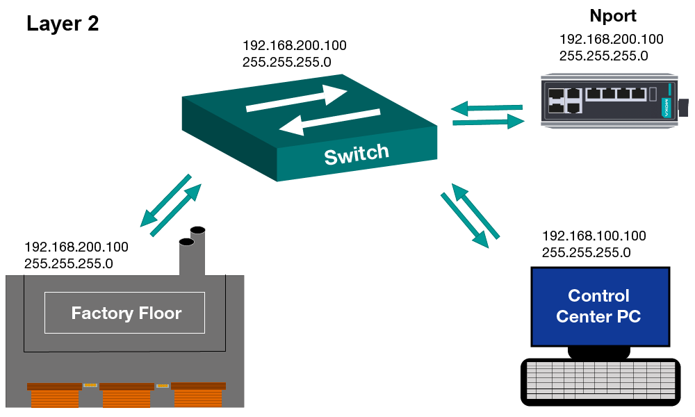
Initially, the customer had connected two separate networks and was attempting to change the IP address of a Moxa Nport device from a different network segment. They were aware they had a different network set up in the environment when they tried to change the device (Nport) IP address from the other network. Although the IP address could be changed from the factory floor, the customer received an error message when trying to change the IP address from the control center PC. After multiple failed attempts, the client and our partner distributor decided to call us.
The Fix
At the distributor’s and client’s request, Christian began trouble shooting the issue after a Q&A session. After this discussion, he was able to draw up a physical topology of the interconnected networks and understand the system requirements.
At first the customer and distributor thought the Nport might have been faulty after having received numerous error messages back from the network from trying to change the IP address using multiple configurations. However, after some light testing Christian was able to conclude that this was not the case.
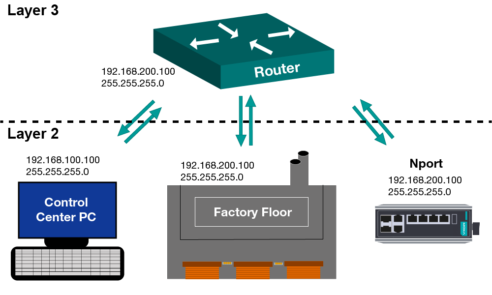
Next he decided to analyze the network topology. Knowing that the main network has been in operational use, Christian focused his efforts on analyzing the new network segment and how the two networks were interconnected. Upon analysis he discovered that the client had merged the networks using a layer 2 switch. This discovery revealed that the error message being transmitted back wasn’t being generated by the Nport, but by the computers in the control room itself. The control room could not actually communicate with the new device on the other network. This was corrected by replacing the layer 2 switch with a layer 3 switch.
The Result
By removing the layer 2 switch and replacing it with a layer 3 switch the issue was resolved. The additional complication was that Moxa provides device discovery tools that work across subnet boundaries by using layer 2 broadcasts and leveraging proprietary communication functions on the device. This is very useful for deployment and trouble-shooting. As a result the customer could "see" or discover the device in this Moxa tool, but when they tried to make changes to the configuration, the communication changed to standard TCP/IP, which for good reasons does not work across network boundaries in this way. After adding this layer 3 device and setting up the appropriate routes to allow for communication between the control center and the new network segment everything worked smoothly. In this example, the switches and the layer 2 network are meant for communicating within a small network or within network segments. A layer 3 switch is meant for communicating between networks or network segments. This is why the network based on the original topology could not see the device on the other network, it wasn’t allowing for proper communication.
Summary

The issue in the network was based on the common misconception that routers, layer 2 switches and layer 3 switches can be used interchangeably. With the original topology, the customer was unable to communicate with devices on the other network segment making them unable to change the IP address on the Nport. Replacing the switch with a layer 3 enabled suite communication between the networks allowing them to change the IP address.
The customer was relieved once the correction was made and even happier to find that there were no further complications with the deployment of their network. Although there was still work to be done until the completion of the factory expansion, the client was pleased that the network had been deployed and would no longer be a cause of worry.
Want to learn more about network design and Ethernet foundations? Try taking our Industrial Ethernet Foundations (IES-F1) course, followed by the layer 2 and layer 3 courses (IES-L2 and IES-L3). These courses are designed and developed by engineers for engineers to ensure what you learn is relevant to what you do.