Nulla facilisi. In vel mauris risus.
Praesent non velit ut libero condimentum pulvinar sed vitae tellus.
Vestibulum id tristique elit. Suspendisse posuere rutrum sodales. Nam id elit ac sem iaculis lacinia posuere vitae metus.
Welcome to episode three of Stories from Tech Support, a series where we interviewed members of our Tech Support and Field Engineering Teams to learn about the challenges they encounter in the field and the solutions used to help overcome their challenges. This series was created to share their experiences and to help others overcome similar problems.
This story comes from Andreas, a Senior Technical Support Engineer here at Moxa. In the story, he tells us about how he worked with an experienced client to get their redundant network to meet ambitious end-to-end recovery time requirements.
The Problem
The customer had set up a Distribution Management System (DMS) and needed a scalable redundant network to support it. They used RSTP and Moxa redundancy protocols in different segments of their nation-wide network. A key characteristic feature of the network are the fiber-networked, distributed, low-voltage feeders (ring main units or RMUs) which were connected on a Moxa Turbo Chain network segment to the upper layer of the mid-voltage substations (transition stations).
The customer deployed the network and began testing. During testing, the network failed to meet recovery requirements. With application-level recovery time of one test as high as 4 minutes, the customer decided to reach out to Moxa’s Technical Support to bring the recovery times into an acceptable range.
The Fix
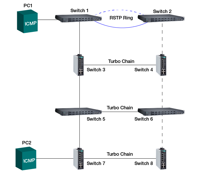
Andreas worked remotely with the customer due to geographical and time constraints. In order to better trouble-shoot the behavior, he staged a test environment with representative mini-models of the real network. Once the model was built, Andreas was able to begin his own tests. Simulating the application by sending pings (= ICMP Ping command) from the upper RSTP network to devices in the lower Turbo Chain network he was able to replicate the observed symptoms.
In the image below, you can see a simplified topology of the scenario at hand. During testing, a ping was sent from PC1 in the upper network to PC2 in the bottom network segment with switch configurations essentially the same as in the field. If this is done during normal network operation, those pings are received by PC2, and the responses are received without issues by PC1. When disconnecting the link between switch 1 and switch 3 the recovery times are sufficiently fast. However, when reconnecting the link, the ping responses for pings being sent right afterwards are not successfully received for an extended period of time. Without going into too much technical detail, this is the expected behavior if the RSTP switches on top are not configured to process the so-called Topology Change Notification messages from the Turbo Chain network below. The technical reason behind is the fact that the RSTP switches would not update their MAC tables quickly enough for the ping to be delivered through the main Turbo Chain link between switch 1 and 3. Switch 1 will still send the information to switch 2 that cannot deliver the information to switch 4 successfully, as the Turbo Chain port on switch 4 changed to blocking mode, no longer allowing data to be received on this port.
Moxa supports the sending of RSTP Topology Change Notification for just this reason: in order to allow all connected network switches with RSTP, Turbo Ring or Turbo Chain enabled to update their MAC tables immediately, when a topology change anywhere in the network is detected. This ensures fast recovery times across complex networks and mixed redundancy mechanisms including RSTP, Turbo Ring and Turbo Chain.
After the appropriate configuration change of the ports on switches 1 and 2 connecting switches 3 and 4 respectively, all recovery issues were resolved.
Result
The simple change in configuration on the RSTP devices allows the RSTP network to understand the related topology change information coming from the Turbo Chain devices. Then the lower network can successfully update the RSTP network when there is a topology change.
Summary
We often have connections between networks. In this case the Turbo Chain network and the upstream RSTP network were connected by two links to ensure redundancy. What happened in this situation was that after recovering the primary Turbo Chain link, the upward network didn’t register the change in topology of the network below. So it thought that it could still send through the same links as before (MAC table not yet updated). The problem only appeared when data was sent from the upward network to devices on the lower network – like a SCADA system polling the status of devices in the field. The system sends out a request to check for device availability or status, but receives no response back. With the correct configuration, the network will now self-heal immediately in case of any such topology changes and the SCADA system can do its job with no or very limited interruptions.